Aluminium
LM4XSA-140*2200*3000
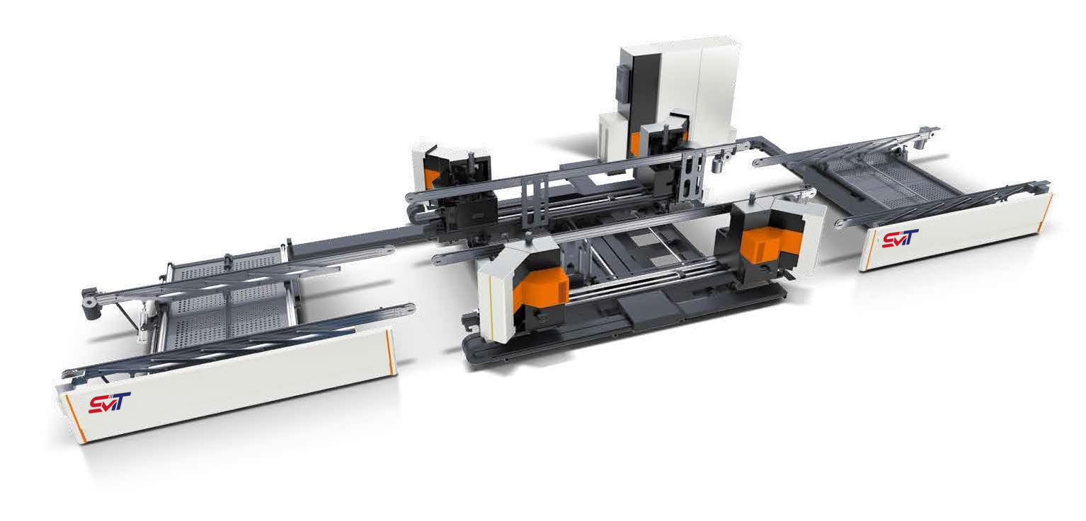
CNC Four-head Corner Crimping Production Line
- Total power
- 50 kW
- Maximum frame
- 3000 × 2200 mm
- Minimum frame
- 700 × 450 mm
 Jinan Smatech Machinery
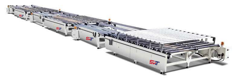 Equipment image for reference. Branding and final configuration are confirmed with your quotation.
Moves and supports window or door assemblies between work positions in an assembly workflow.
Moves and supports window or door assemblies between work positions in an assembly workflow. It handles the workpiece; it does not perform cutting, milling or corner crimping itself.
Modular handling sections can help organise the workshop around assembly tasks. The station count and layout are project-specific, and the catalogue speed value lacks a time unit.
Jinan Smatech Machinery Enterprise Co., Ltd. can review your requirement against this catalogue configuration when preparing a quotation.
Check this model for my part →Application examples are starting points for selection. Actual compatibility depends on the profile, tooling and required result.
Electrical power in kW is not the supply voltage. Confirm voltage, frequency and phase for the destination workshop.
Catalogue reference: physical page 16. Check your profile drawing and power supply before ordering.
The catalogue does not state the time unit for conveyor speed. Speed is not used for selection.
| Motor per section | 0.75 kW |
|---|---|
| Transported frame width | 2000 mm |
| Transported frame height | 180 mm |
| Section length × width | 2800 × 2500 mm |
Section dimensions and transported workpiece limits must be checked separately when laying out stations.
The catalogue speed entry has no time unit. A verified conveyor speed is required before estimating transfer time.
The catalogue does not provide a separate confirmed standard/optional supply list. Tooling, electrical compatibility, software where applicable, installation and service scope are confirmed with the quotation.
Request a written supply list for your model, including tooling and any project-specific accessories.
Frame sizes; profile and corner connector drawings; joining tool arrangement and process layout.
Include a representative part drawing, required finish, target output and workshop power supply. This allows the quotation to address the actual machine configuration.
CNC Four-head Corner Crimping Production Line
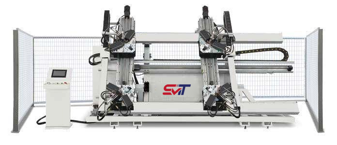
CNC Four-head Corner Crimping Machine
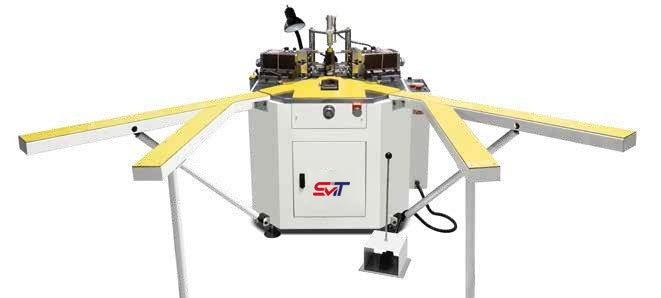
Heavy-duty Single-head Corner Crimping Machine